

Overview
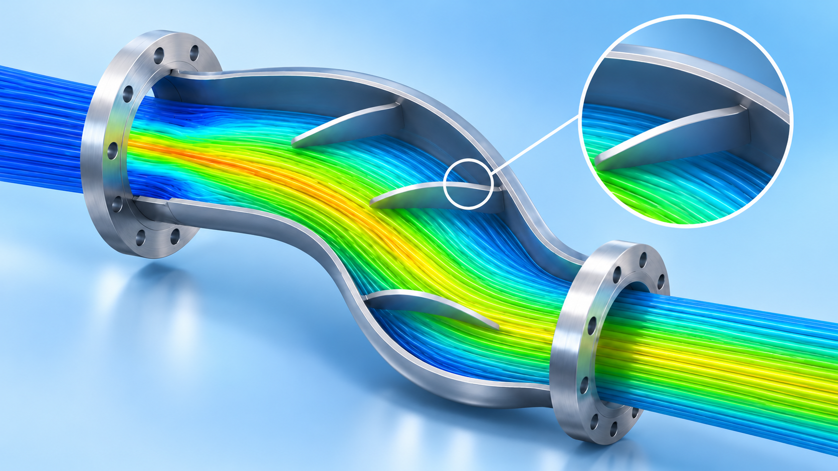
Sudden flow fluctuations and aerodynamic impacts within duct systems are primary causes of system vibration and structural failure. In this study, we predict the flow stabilization effects according to guide vane design variables through CAE simulation, and present validation processes for optimal geometric configurations to minimize flow impact and ensure structural safety.
1. How to evaluate the flow impact of guide vanes?
The topic we will cover today is “improving fluid flow” in structures.
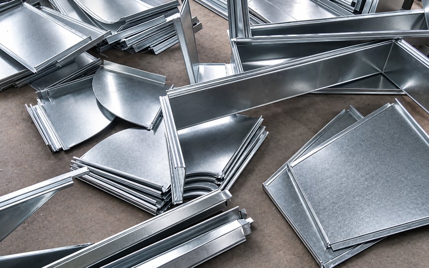
SCR denitrification equipment in thermal power plants is used to remove nitrogen oxides (NOx) from exhaust gas through catalytic reactions. In this process, the exhaust gas must be supplied uniformly to the catalyst layer to improve reaction efficiency and ensure stable denitrification performance.

The duct structure of an SCR system is difficult to evaluate directly because it handles high-temperature exhaust gas and is generally large in scale. In addition, direct observation of the internal flow behavior is limited during operation. Therefore, CFD analysis is commonly used during the design stage to visualize internal flow characteristics and evaluate flow uniformity.
2. Why analyze SCR duct flow?
In SCR duct design, guide vanes are often applied to improve the flow path without significantly modifying the overall duct geometry. By adjusting the guide vane layout, engineers can reduce flow separation, high-velocity regions, and non-uniform flow distribution before the exhaust gas reaches the catalyst.
This example focuses on the internal flow analysis of a duct structure in a thermal power plant SCR denitrification system. The objective is to evaluate the exhaust gas flow distribution, identify recirculation and flow separation regions, and improve flow uniformity through guide vane design.
3. Flow Path Optimization Using Guide Vanes
Guide vanes are commonly used to improve flow distribution and guide fluid flow in a desired direction. By installing thin plate-like structures in the flow path, engineers can reduce flow separation, suppress recirculation, and improve flow uniformity without significantly modifying the overall structure.
Guide vanes are widely applied in various systems, including set-top boxes, computers, electronic equipment, and industrial facilities. Compared with redesigning the entire structure, guide vane installation is often a more economical and practical approach. In addition to improving flow characteristics, guide vanes may also contribute to local structural stiffness depending on their configuration.
.....
Explore the Full Resource
Get practical insights, proven approaches, and real-world engineering examples