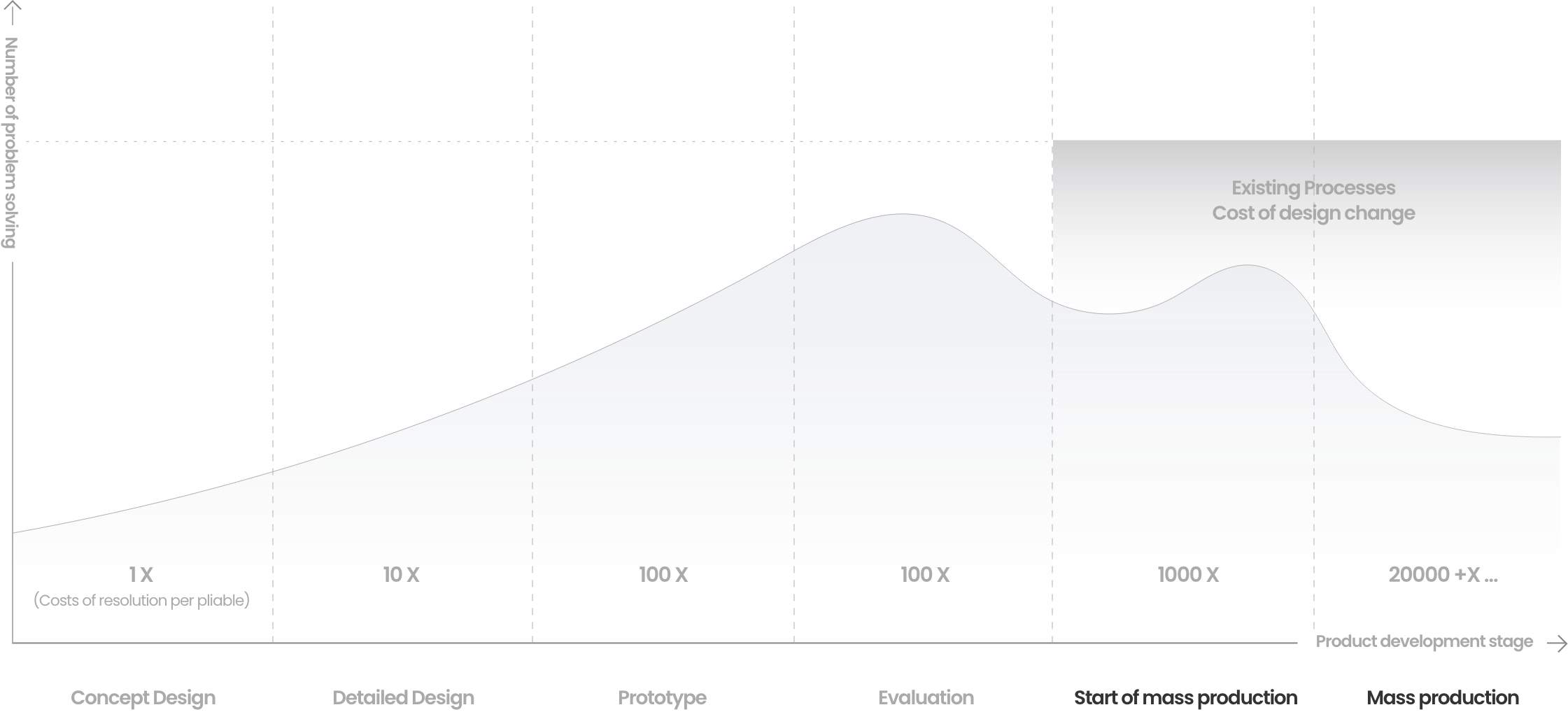
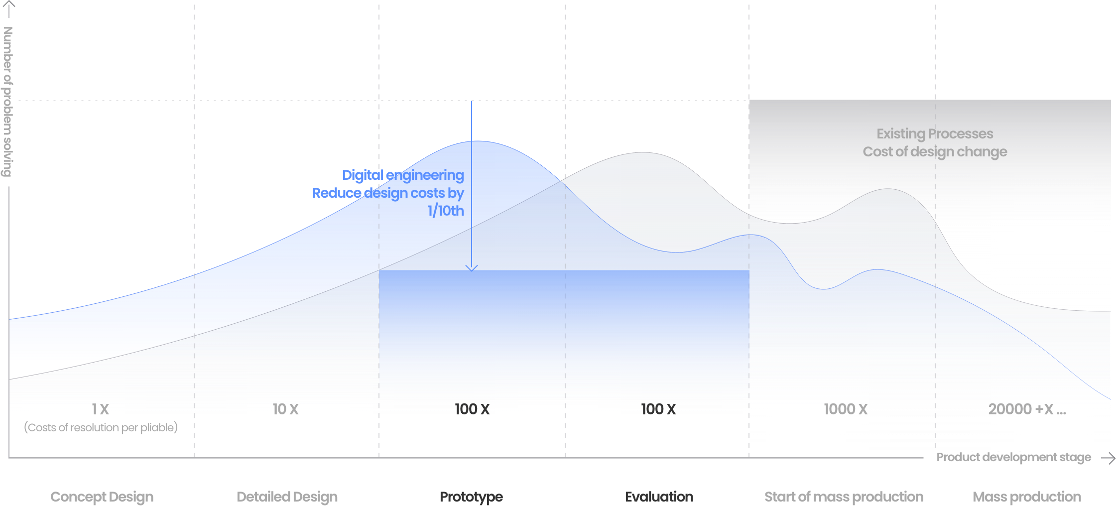
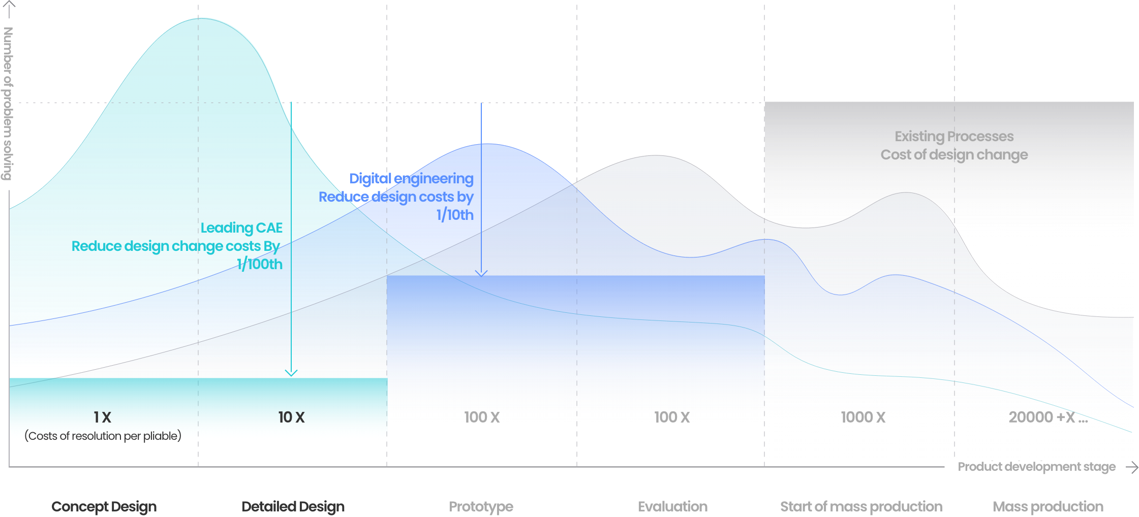
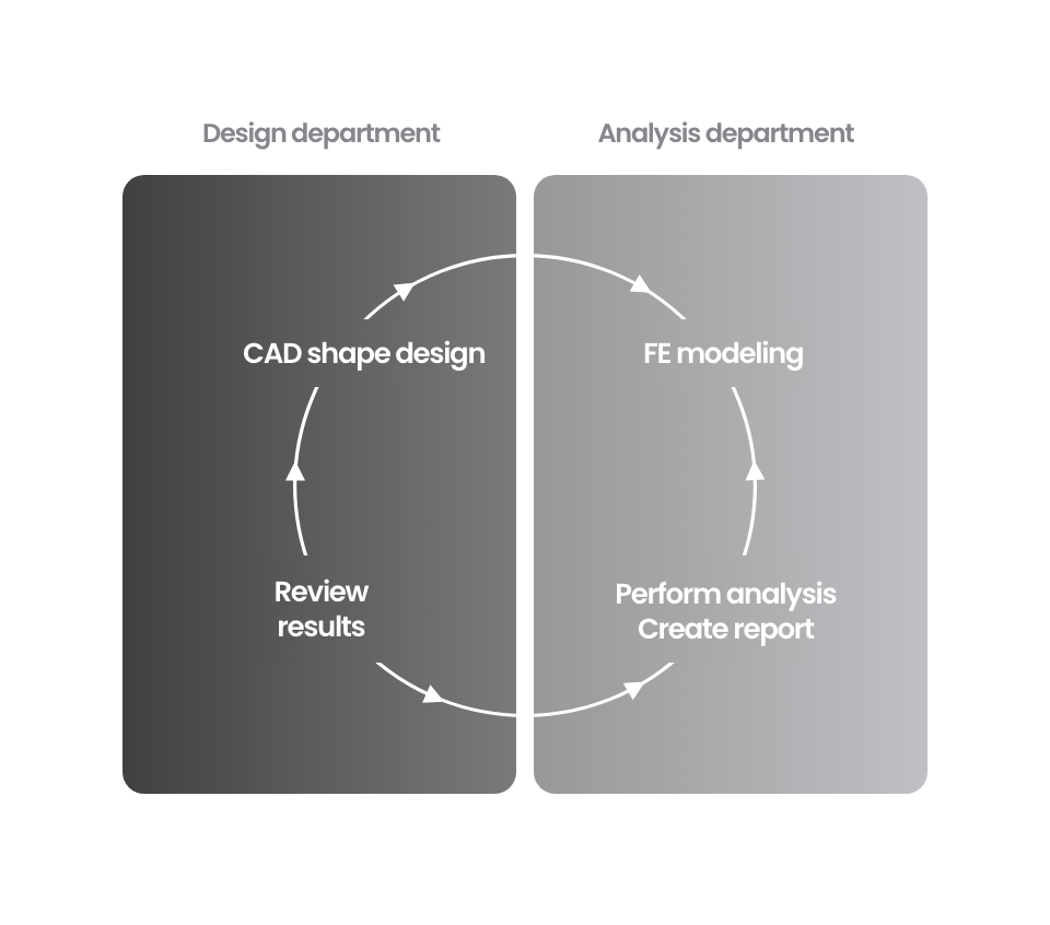
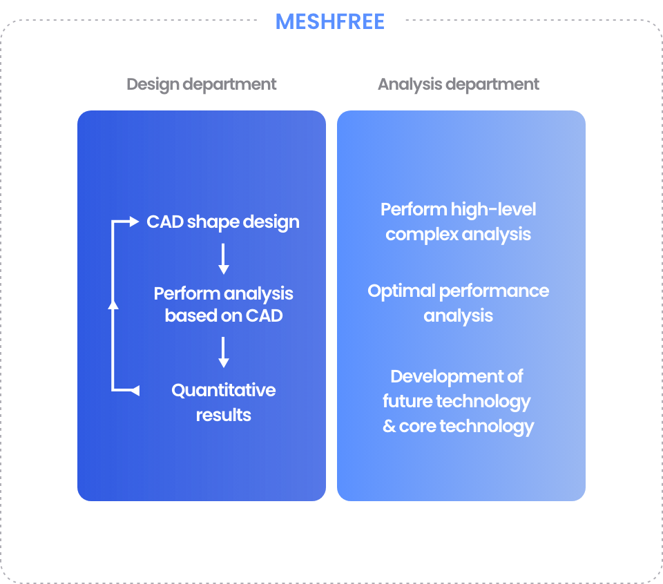
Most convenient

midas MeshFree

Go to try
Become precise and
intuitivewithout meshes

Midas MeshFree’s proprietary IBM
(Implicit boundary method) algorithm
is a technology that enables accurate analysis without the need to create meshes, which allows design engineers to simulate intuitively. MeshFree created a new innovation with making the creation of meshes unnecessary.

WHY MeshFree The purpose of
simulation is to find and
solve
problems
in the design phase.

During the design phase, it is very important to review
the various designs. The more you validate your design with virtual prototypes, the more you can help reduce overall costs.

Optimal design quickly
and clearly with quantitative
values derived by designers
Meshfree supports you to make
decision quicker in situations
when the
conditions in the design stage constantly
change by quickly deriving quantitative
values based on the changed CAD model.
This also supports you to try our
more free and innovative designs
in the linear design stage.

Design engineers
like analysis experts
Go to try
3-STEP Process A process
that is completed
in one, two, three
Step 1. Import CAD model In addition, in order to import
a designed shape without the
clean-up process, the material
information for each parts and
connection definitions between
parts are automatically/conveniently defined.
Step 2. Setting Analysis Conditions Complete your desired analysis
settings at once without making mistaking
by easily following the guidelines of difficult
analysis conditions.
Step 3. Analysis and View Results Reduction of work time by
at least 60% with background
sorted grid technology without
mesh work, as well as accuracy
within 5% of error rate
Step 1. Import CAD model In addition, in order to import
a designed
shape without the
clean-up process,
the material
information for each parts
and
connection definitions between
parts are automatically/conveniently defined.
Step 2. Setting Analysis Conditions Complete your desired analysis
settings
at once without making mistaking
by easily following the guidelines of
difficult
analysis conditions.
Step 3. Analysis and View Results Reduction of work time by
at least 60%
with background
sorted grid technology
without
mesh work, as well as accuracy
within 5% of error rate
Smart Guide Where only
what is needed

This function provides only the necessary load/boundary conditions for the desired analysis type.
Confusion caused by unnecessary buttons has been greatly reduced.

Auto-Update Even with tens of thousands of
design changes
with a single condition
input, the load and boundary
conditions
are automatically applied.
Design Review & Synchronization View Various results at a glance

The result value comparison function is a function that allows you to compare and analyze various design changes in one window.
You can check the stress maximum value, minimum value, volume, and mass change. Through the synchro alignment function, you can simultaneously move the comparison model to a desired angle and use it in a variety of reports.

Verification you can trust Easy but accurate
midas MeshFree

MeshFree has completed reliability verification tests by the National Association for Mechanical Engineering (NAFEMS) and the Samsung Global Technology Center.
In addition, its accuracy has been verified by various official machinery organizations such as the National Federation of Technical Societies and Public-Private Joint Investment Technology, and many companies are using it.

More NAFEM Validation Materials
Project Application Powerful Meshfree
analysis function
Linear Static Analysis Analyzes large-scale, sophisticated models
quickly and accurately.

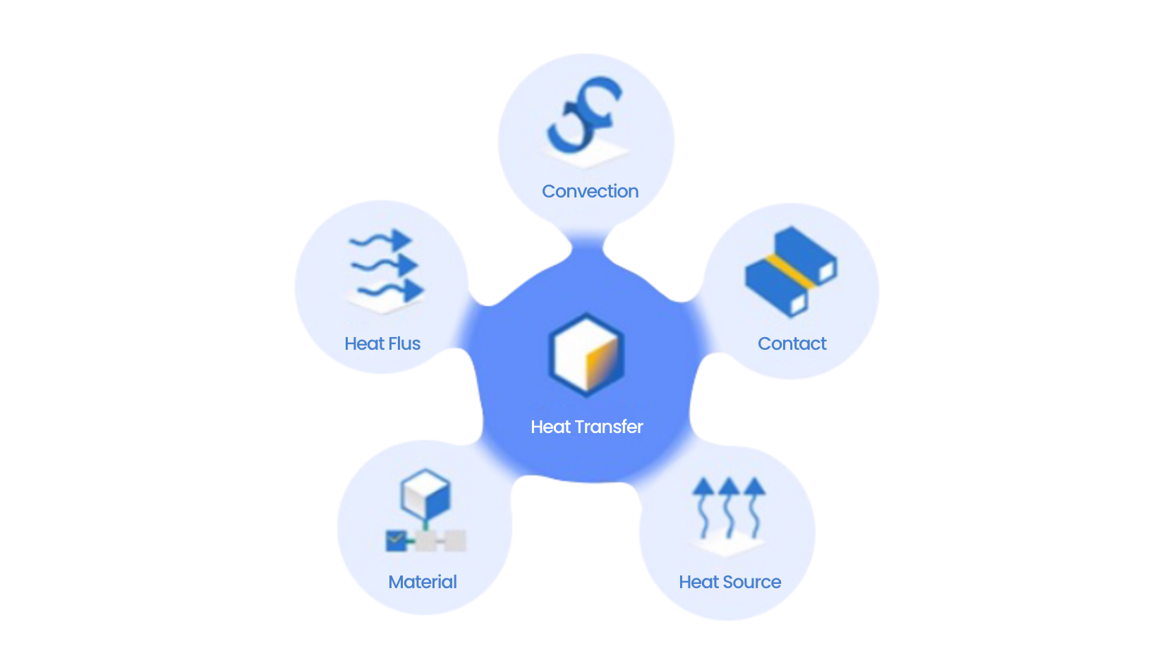
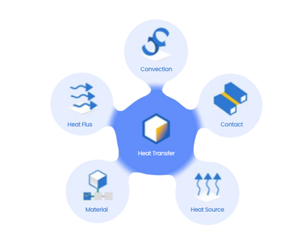
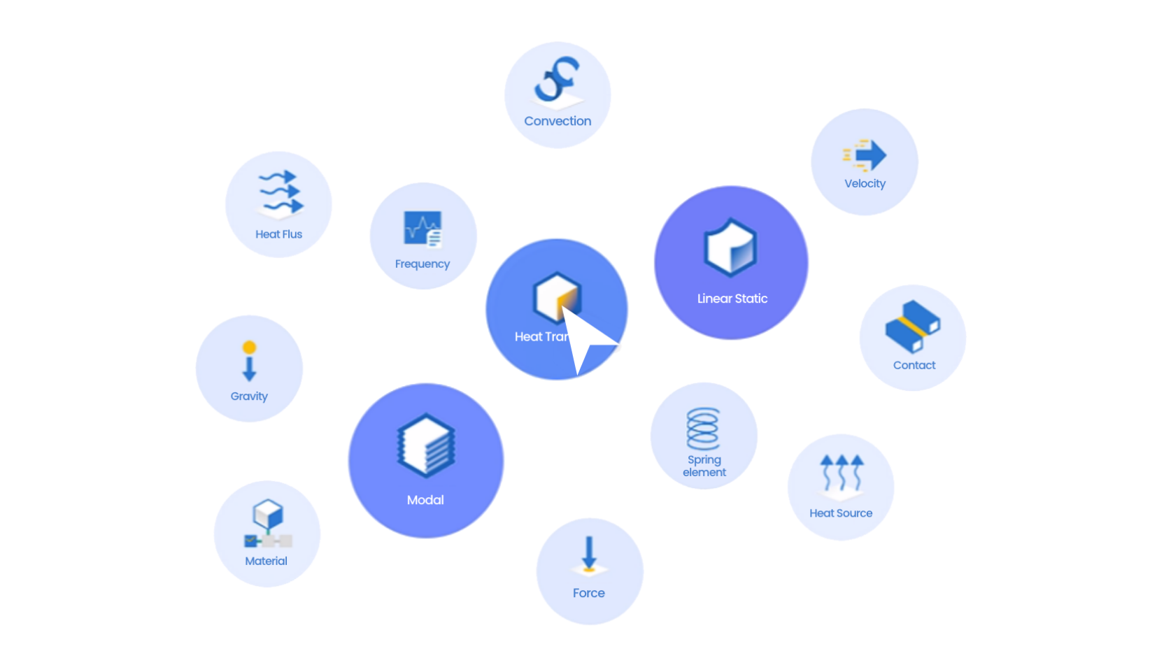
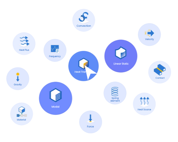
Suitable for models including complex NURBS Patches and Sliver Faces Provides rigid body and spring element features Linear contact support (Bonded / Bi-directional Sliding / General Contact) Support for various and practical load and boundary conditions Support for thermal deformation and thermal stress analysis due to temperature loads

Analyzes large-scale, sophisticated models quickly and accurately without cleanup.
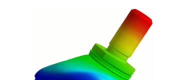
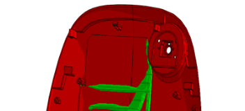
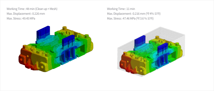
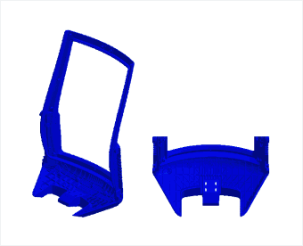
Stiffness Evaluation of Major Automotive Parts

- Applicable to models with complex NURBS Patches and Sliver Faces
- Perform stiffness evaluation using the original CAD model without a simplification process

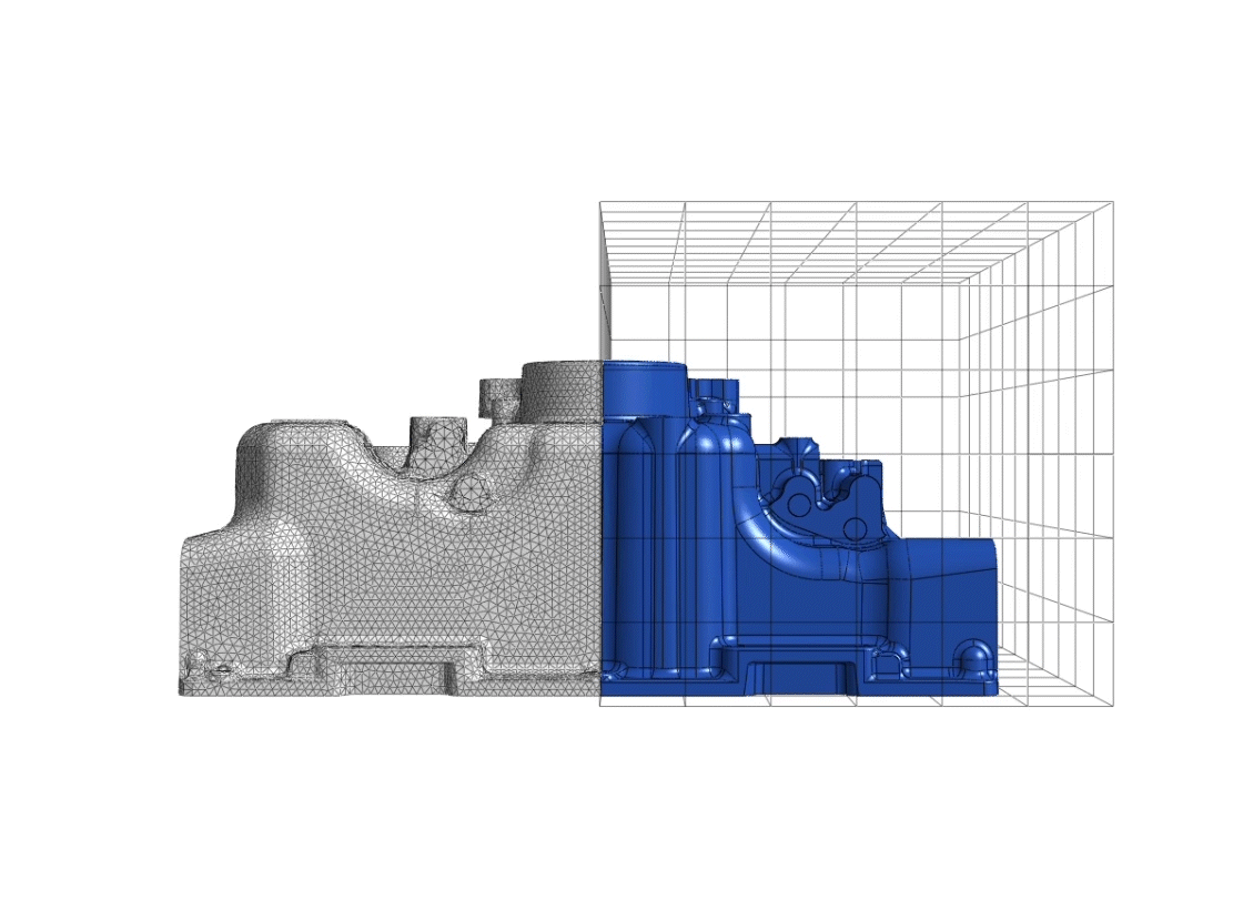
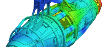
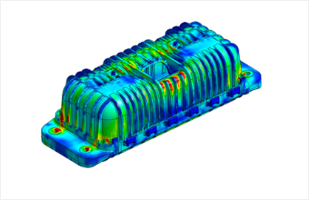
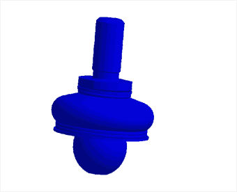
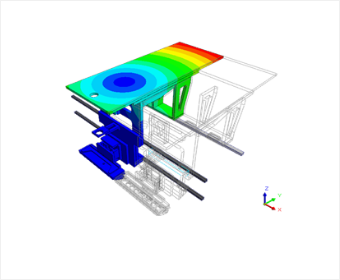
Engine Assembly Stiffness Evaluation

- Stiffness evaluation utilizing the CAD model without simplification and idealization processes
- Connecting numerous assembly components by applying linear contact conditions

Even large-scale assembly models can be analyzed utilizing linear contact.
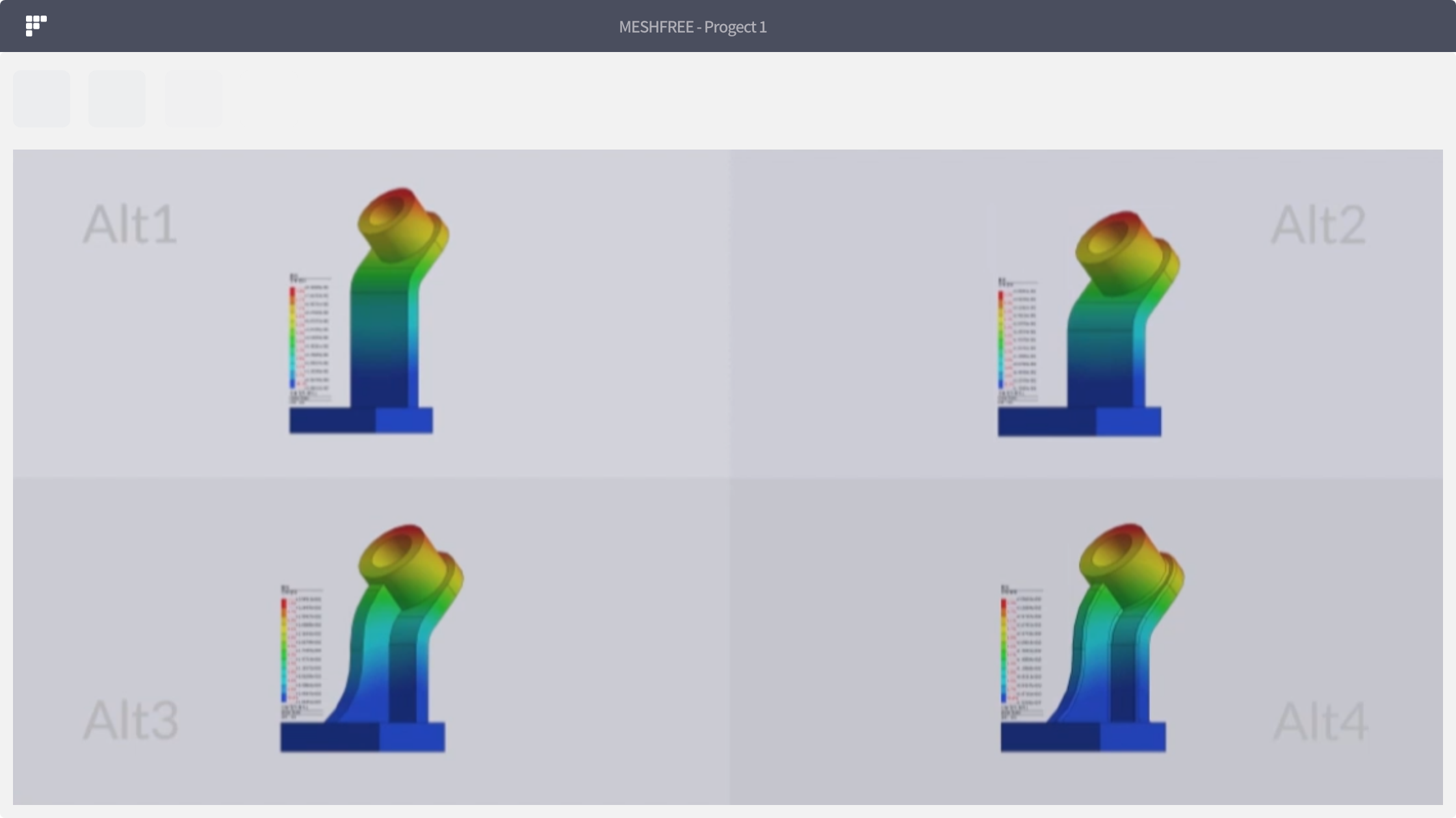
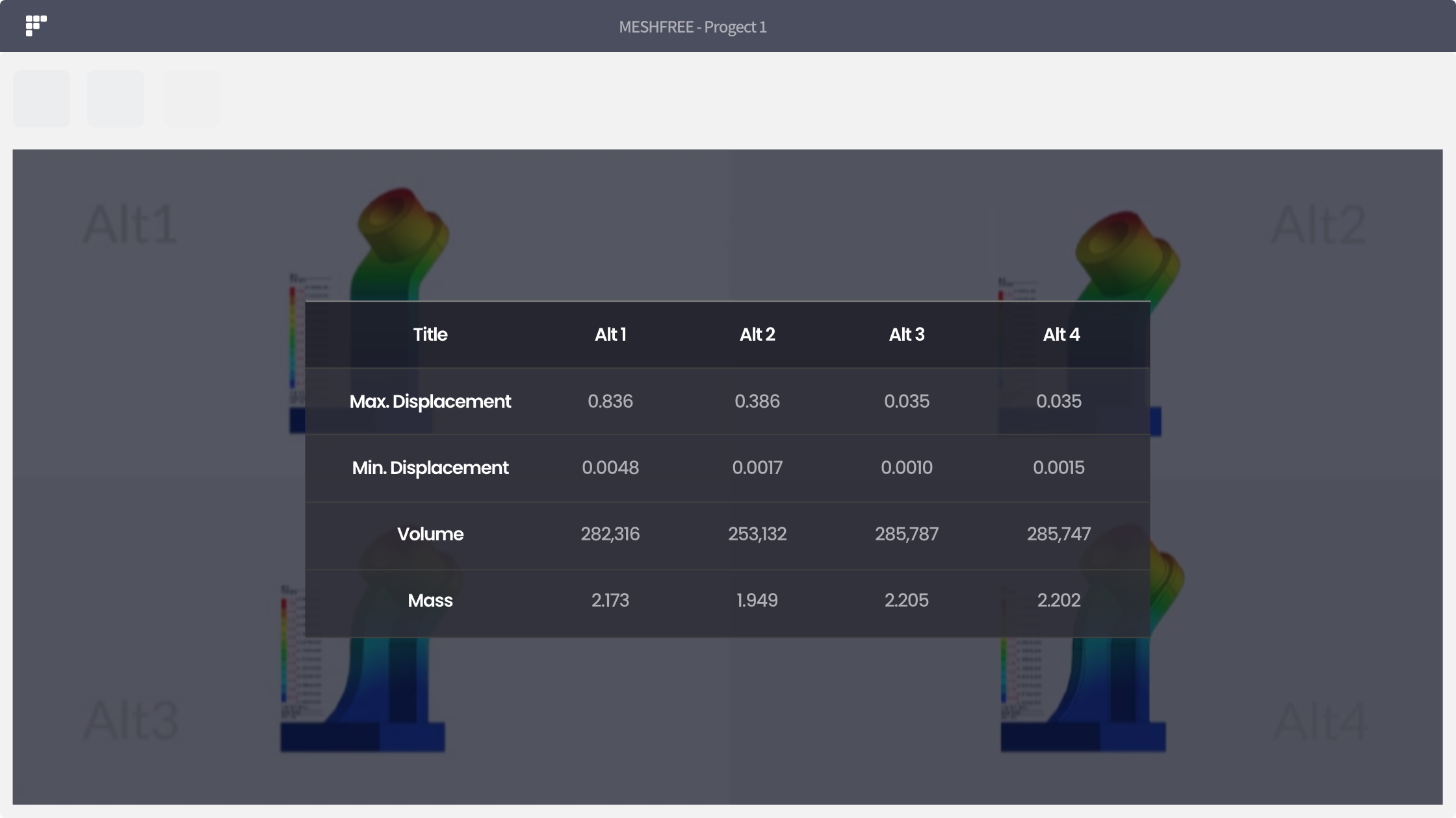
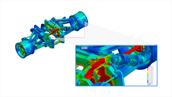
Structural Safety Analysis of Vehicle Suspension

- Safety review through analysis of suspension displacement and stress under load application
- Analysis of maximum displacement and stress components occurring under vehicle load application
- Utilize the original CAE model directly without performing model simplification and idealization

Although working time is drastically reduced, reliability remains unchanged.
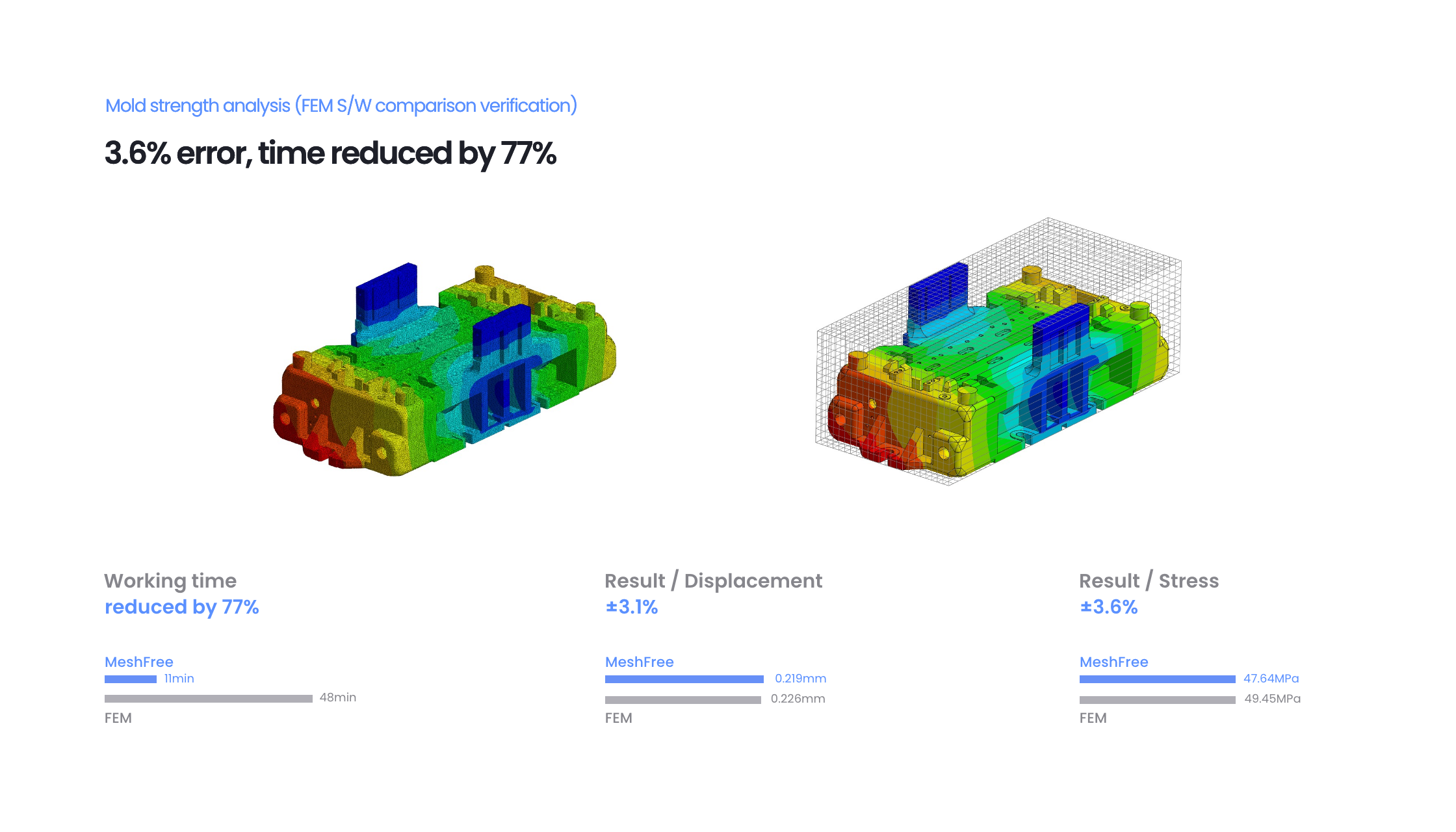
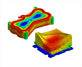
Mold Strength Analysis

- Mold strength evaluation under self-weight and major vertical load application
- Verification of analysis time and results against FEM results

Even in linear static analysis, rapid assessment is possible utilizing general contact.
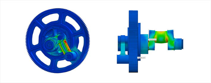
Gear Failure Cause Analysis

- Operating mechanism analysis and Load Path analysis to calculate operating loadsCheck for potential failure in bolt areas and link connection parts by applying general contact conditions

Nonlinear Static Analysis Adding nonlinearity to MeshFree.

Support various iterative methods, stiffness update method and convergence criterion method Material nonlinearity
: Elasto-Plastic Model
: Hyper-Elastic Model
Geometric Nonlinearity
: Large Deformation
: Large Rotation
: Follwing Force Support
Contact Nonlinearity
: General Contact Support

More realistic analysis is possible through geometric nonlinear analysis.
Medicine case in heat chamber

- Thermal deformation according to temperature distribution
- Deformation analysis considering general contact condition and large deformation

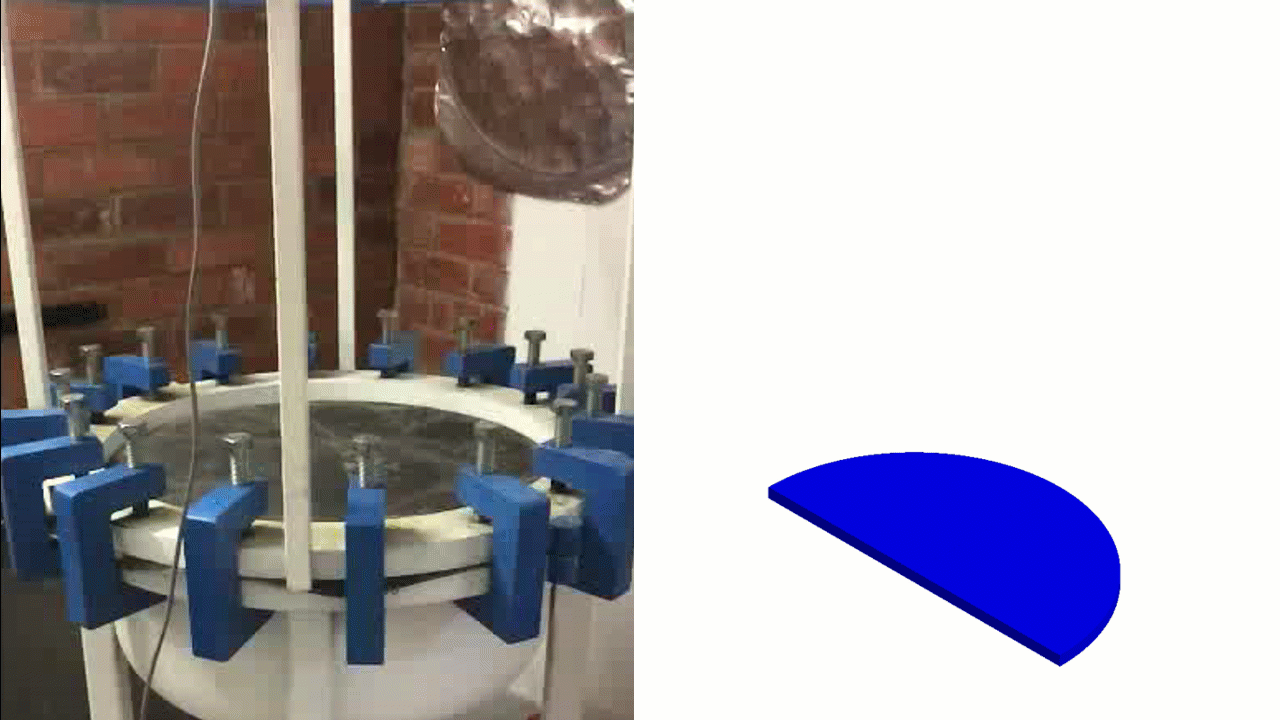
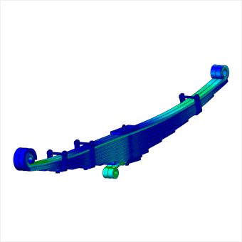
Analysis of plate spring strength and rigidity

- Geometric nonlinear analysis considering bi-directional sliding contact

Elasto-plastic models and hyperelastic models are also supported without issue
Backrest Strength Simulation Applying BIFMA Standards

- Checking for potential failure by applying Functional load and Proof load
- Applying elasto-plastic model and geometric nonlinearity

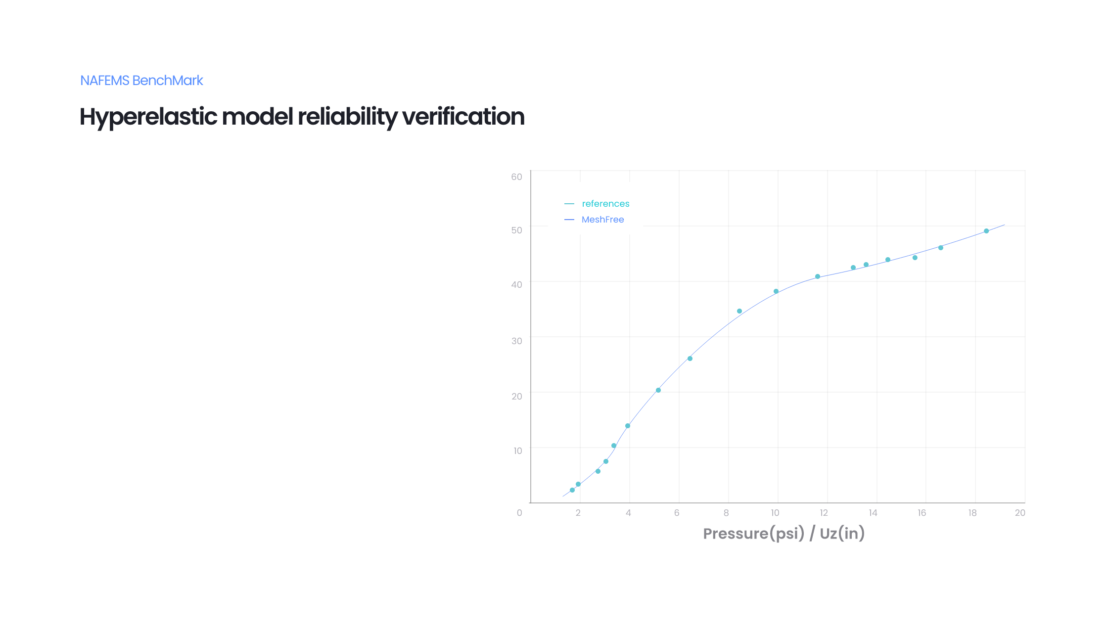
Performance analysis of rubber materials

- Application of material nonlinearity using hyper elastic materials
- Application of geometric nonlinearity considering large deformation
- Linear contact condition applied

Modal Analysis Fast eigenvalue analysis
of large-scale assembly models is possible

Natural Frequencies and Mode Shapes Calculation of Modal Participation Rate, Effective Mass and Calculation Error Check Strum Sequence Check within the Specified Eigenvalue Range (Check for Missing Eigenvalues) Possible to Consider Prestress Linear Contact: Welded Behavior, Sliding

Fast eigenvalue analysis of large-scale assembly models is possible.
Engine Block Natural Frequency Analysis

- Natural frequency analysis of an engine block composed of 140 parts
- Execute natural frequency analysis utilizing the model designed without mass and spring element idealization

Designers can perform reviews quickly using the design model directly.
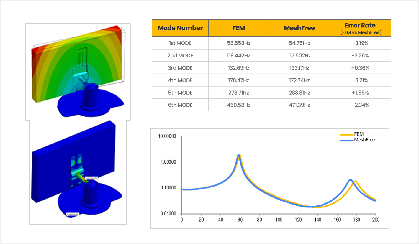
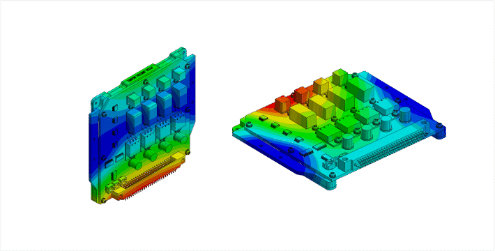
Switch Module Natural Frequency Analysis

- Natural frequency analysis of the existing design for resonance avoidance purposes
- Natural frequency analysis of various design alternatives to improve existing vibration performance
- Analysis performed directly by design engineers on a model composed of 100 parts
- Weld contact defined for major connection parts

Although working time is drastically reduced, reliability remains unchanged.
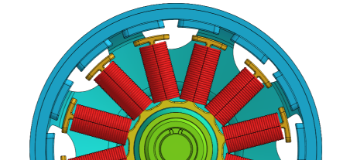
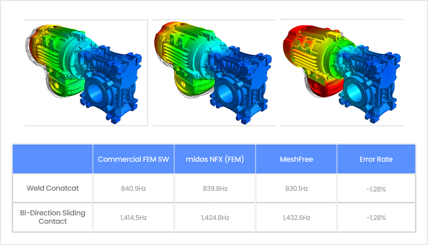
Gearbox Dynamic Characteristics Analysis

- Generation of gearbox vibration due to motor operation
- Review of potential resonance occurrence in the gearbox due to vibration and subsequent avoidance design
- Reliability verification against FEM results

Linear Dynamic Analysis Various analyses can be performed
using direct integration and modal superposition methods.

Direct Method and Modal Method Analysis Transient Response Analysis Frequency Response Analysis Random Vibration Analysis Response Spectrum Analysis Design Spectrum Database for International Standard Various Damping Effects
(Modal damping, Frequency Dependent)

Effects due to impact loads or equipment movement can be reviewed using transient response analysis.
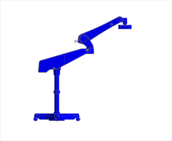
Laser Inspection Machine Operational Stability Evaluation

- Operational stability evaluation of the inspection machine due to rapid acceleration/deceleration
- Perform analysis considering Enforced motion and Damping effects

Medical Device Support Impact Simulation

- Safety review of the support stand upon application of instantaneous impact load
- Determination of deflection amount and vibration damping time upon impact load application

Dynamic characteristics can be analyzed through frequency response analysis.
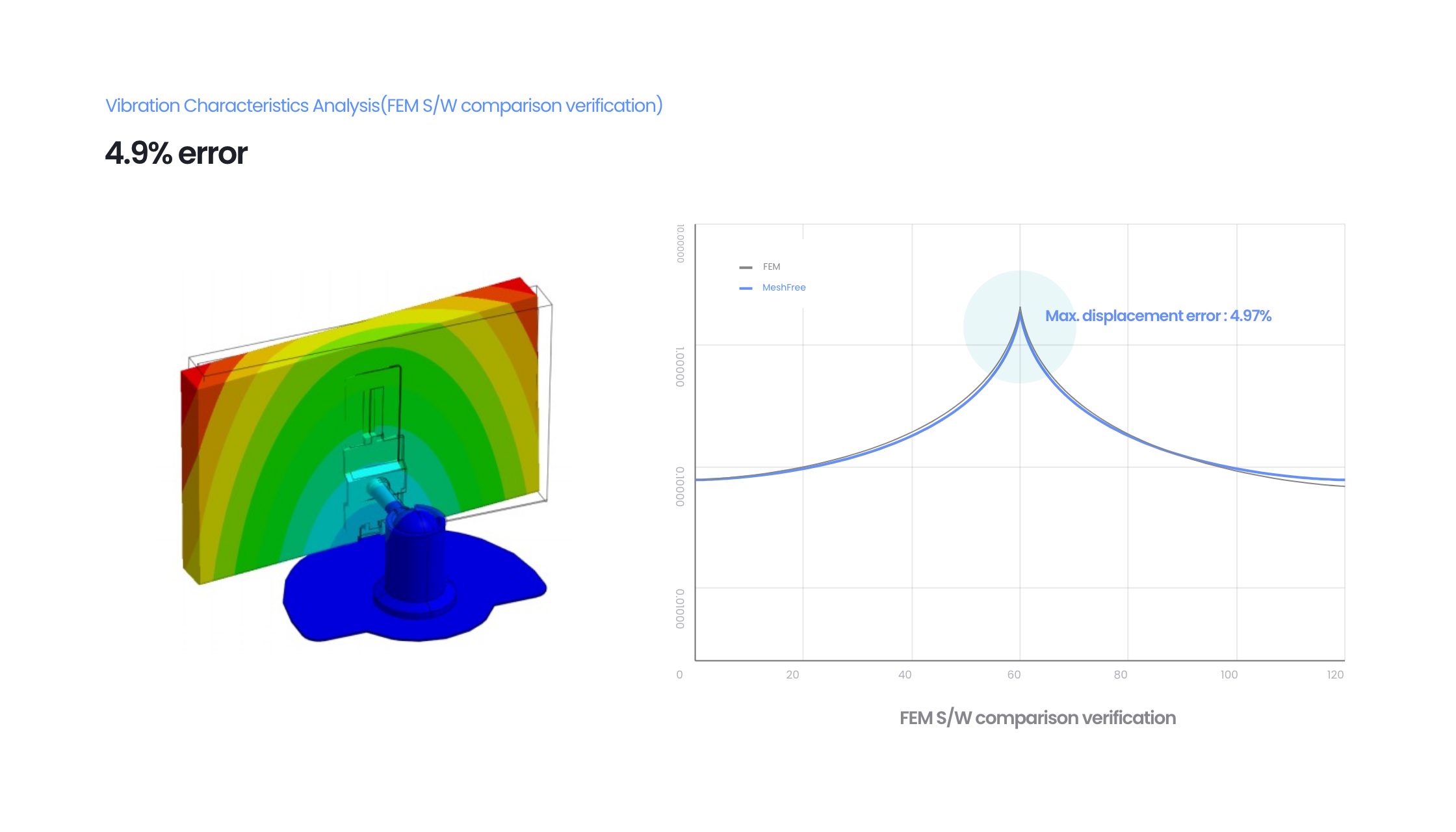
Automotive Monitor Dynamic Characteristics Analysis

- Automotive monitor dynamic characteristics analysis through modal analysis and frequency response analysis
- Result comparison and verification against FEM analysis

Failure probability for random loads can be analyzed through random vibration analysis.
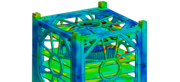
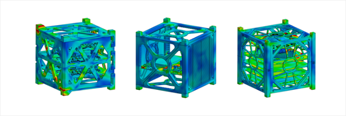
CubeSat Random Vibration Analysis

- Random vibration safety review for various types of CubeSats
- Review of 3-Sigma RMS stress for each direction

Safety against earthquake loads can be ensured based on country-specific design codes.
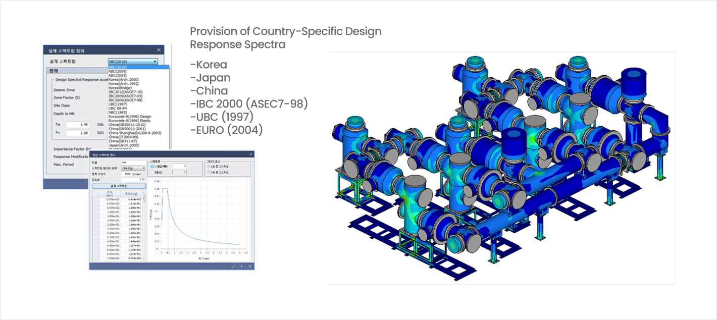
Gas Insulated Switchgear (GIS) Seismic Verification

- Seismic performance verification based on KBC 2009 standards
- Assessed by applying modal combination methods such as CQC, ABS, SRSS, NRL, TENP, etc.

Heat Transfer Analysis Heat transfer / thermal stress analysis is possible
with support for practical conditions.

Steady-state Heat Transfer Analysis Transient Heat Transfer Analysis Support for various load conditions such as heat generation, conduction, convection, radiation, heat flux, etc. Support for thermal contact function to implement heat conduction between discontinuous parts.

Cooling performance can be assessed by applying various heat generation and material conditions.
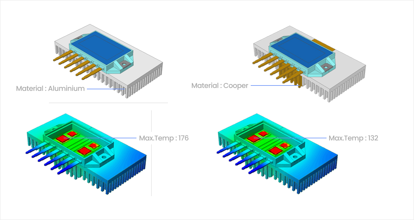
MOSFET Heat Sink Cooling Performance Improvement

- Cooling performance enhancement by increasing heat dissipation area
- Cooling performance enhancement by changing material

Various design alternatives can be quickly evaluated in the design phase.
Temperature Evaluation due to LED Chip Heat Generation

- Assembly model with a total of 152 Parts
- Application of fixed temperature and natural convection conditions
- Application of Weld contact condition utilizing automatic contact
- Thermal deformation review through coupled thermal-structural analysis

Assessment is also possible for temperature loads that change over time.
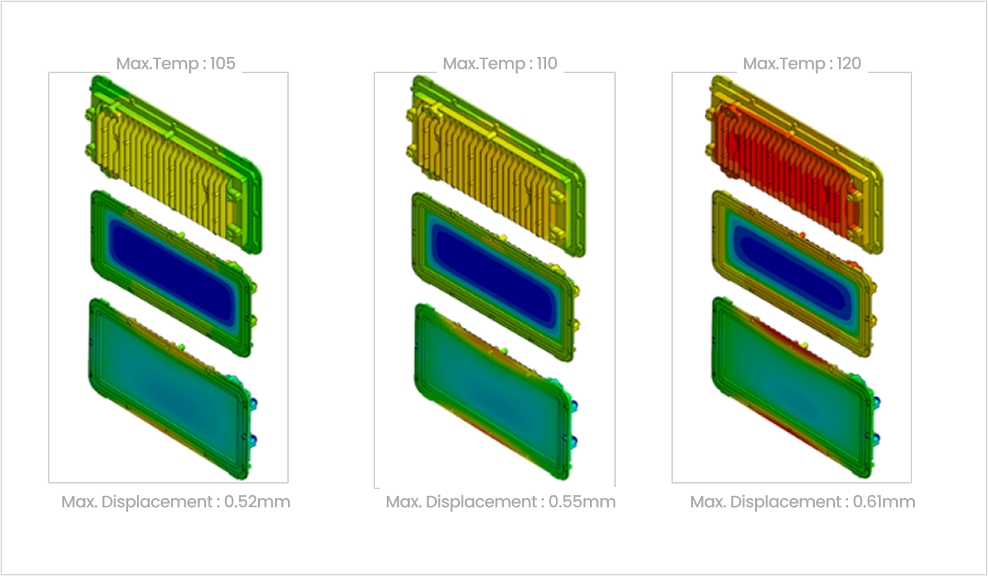
Chipboard Transient Heat Transfer Analysis Comparison and Verification

- Transient heat transfer analysis of the chipboard according to various thermal load inputs
- Reliability comparison and verification against FEM analysis results

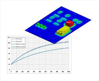
Sheath Heater and Housing Jig Transient Heat Transfer Analysis

- Examination of temperature variation according to time-dependent heat generation conditions

Topology Optimization Topology optimization design
considering static/modal analysis and manufacturing processes

Optimized Analysis Function with Static Analysis and Modal Analysis Topology optimization design considering constraints and process conditions

Finds the optimal shape starting from the original CAD design.
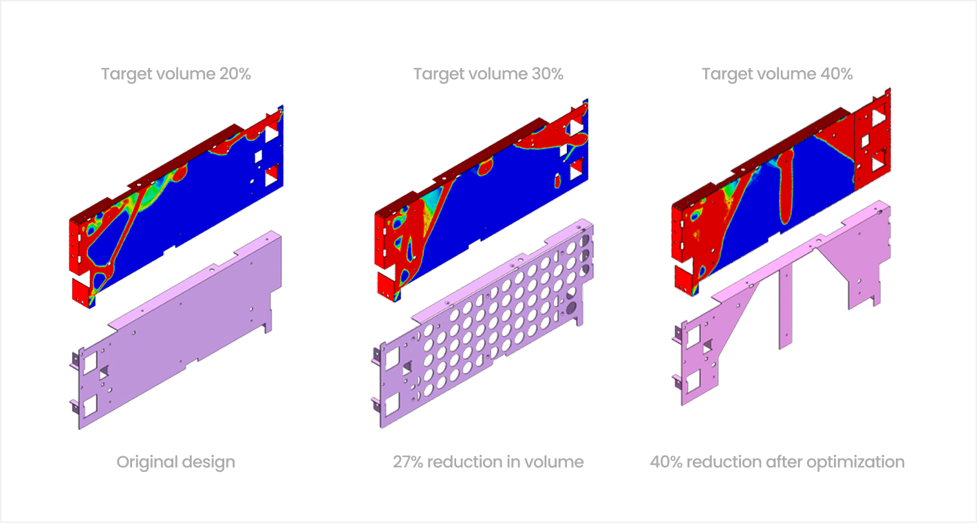
Optimal Design of Bracket Shape for Stiffness Retention

- Derive a design proposal for the product's bracket that maintains stiffness while allowing for lightweighting.
- Achieve up to 40% target volume reduction through topology optimization design.

Optimal design reflecting various field conditions is possible utilizing manufacturing conditions and constraints
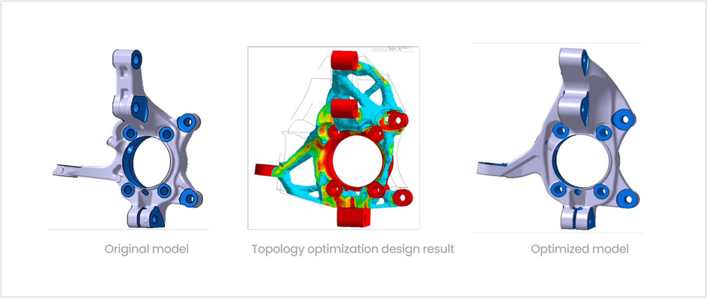
Derivation of Optimal Shape for Automotive Knuckle

- Optimal design applying displacement constraints and multiple load conditions
- 39% performance improvement compared to the original design, despite minimal material reduction.

Check out more questions
about MeshFree
  • What are the minimum system specs?

    Minimum: Ram 16GB / CPU intel i3 / HDD - 100GB or more free space / NVIDIA Graphic card required / OS - Windows 64bit
    Recommended: Ram 32GB / CPU intel i5 / HDD - 100GB or more free space / NVIDIA Graphic card required / OS - Windows 64 bit

  • What is the difference between CAD embedded software and Meshfree?

    The analysis purpose of CAD embedded SW is for designers to easily analyze. However, it is the same regardless of SW that designers have to go through mesh and clean-up for analysis and there are many things to know. Meshfree is a program with high scalability for designers by minimizing the time required for analysis and the information they need to know.

  • If it can be used without specialized knowledge, is it possible to perform difficult analysis?

    MeshFree is basically equipped with FEM level analysis function. In addition to linear analysis, modal analysis, and heat transfer analysis, which are mainly used in the design stage, all analyzes including nonlinear static analysis and dynamic analysis are available. Even for advanced analysis, it is easy to use based on the 3-step process.

  • How is the tendency/accuracy of the analysis results between Meshfree and FEM?

    The tendency appears to be the same. However, while FEM involves a high-cost work called Mesh for analysis to determine the degree of tendency, Meshfree can perform everything from tendency analysis to precise analysis only by adjusting the grid size. In the case of the Korean Society of Mechanical Engineers verification model, the error rate is around 5%, and NAFEMS also performed verification with FEM. However, due to the characteristics of the product, it is more useful to use MeshFree to quickly compare and review various design proposals in the early design stage to understand the performance rather than to derive precise results.

  • How do you mainly use MeshFree?

    MeshFree is mainly used when you want to check the performance of a product at the design stage. I n the case of Samsung Electronics and LG Electronics, designers are using it as a way to find and solve problems by identifying product performance in advance centered on designers in the design stage, and through this, they are innovating the design process.