

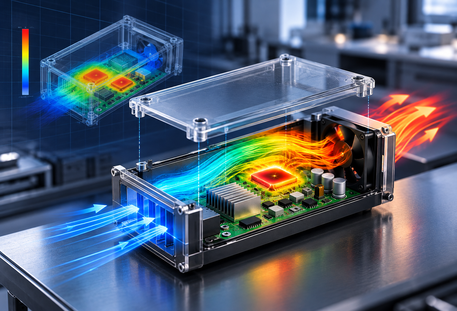
Overview
1. Electronic Equipment Thermal Flow Analysis
Electronic equipment contains a wide variety of components, including PCBs, semiconductor chips, and electronic devices. To improve design accuracy and product reliability, it is essential to understand and properly represent their thermal behavior.
Various thermal phenomena can occur within electronic equipment. Layered conductor-insulator structures in PCBs introduce anisotropic thermal conductivity, while internal package structures in semiconductor devices can generate significant thermal resistance.
One of the most important considerations during thermal design is the operating temperature of heat-generating components. More specifically, engineers must evaluate the junction temperature of semiconductor devices to determine whether performance degradation, reliability issues, or even fire hazards may occur. The question then becomes: how can these effects be accurately represented in a thermal-fluid simulation?
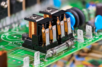
Electronic Equipment
2. Why Use PCB and Thermal Resistance Models?
The primary objective of electronic equipment thermal analysis is to understand how internally generated heat is transferred to the surrounding environment and how the resulting temperature rise affects system performance.
Printed circuit boards typically consist of alternating layers of conductors and insulating materials. As a result, thermal conductivity varies depending on the direction of heat transfer, a phenomenon known as anisotropy. To accurately represent this behavior, direction-dependent thermal conductivity values must be calculated and applied instead of assuming isotropic material properties. Dedicated PCB thermal property calculation functions allow realistic thermal behavior to be reproduced without explicitly modeling every layer.
For semiconductor packages, the internal structure is often complex and the primary heat source is located at the chip junction. Rather than directly modeling all internal details, thermal resistance models are widely used. When thermal resistance values such as θjb (junction-to-board) and θjc (junction-to-case) are available, a two-resistance model can accurately predict junction temperatures while significantly reducing modeling complexity. This approach enables engineers to rapidly evaluate various thermal scenarios during early design stages and is indispensable for product performance prediction and reliability assessment.
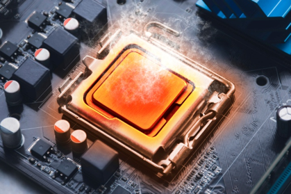
Thermal analysis
3. What Should Be Considered in Electronic Equipment Thermal Flow Analysis?
Thermal-flow analysis of electronic equipment extends beyond conventional heat transfer calculations. The primary objective is to predict the interaction between airflow and heat transfer under actual operating conditions. Heat sources are generally distributed throughout the electronic assembly, and both their locations and magnitudes have a significant influence on cooling performance. Therefore, the heat generation profile and cooling method (natural convection or forced convection) should be clearly defined during the early stages of model development.
.....
Explore the Full Resource
Get practical insights, proven approaches, and real-world engineering examples